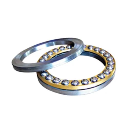
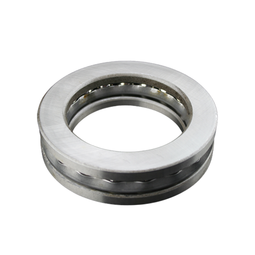
The thrust ball bearing consists of three parts: the seat ring, the shaft ring and the steel ball cage assembly. The shaft ring that matches the shaft is called the shaft ring, and the seat ring that matches the housing is called the seat ring.
According to the force analysis, it is divided into a one-way thrust ball bearing and a two-way thrust ball bearing. The one-way thrust ball bearing can withstand a one-way axial load. The two-way thrust ball bearing can withstand a two-way axial load, in which the shaft ring matches the shaft. The mounting surface of the seat ring is a spherical bearing, which has self-alignment performance and can reduce the impact of installation errors. Thrust ball bearings cannot withstand radial loads and have a relatively low limit speed.

Although the installation operation of thrust bearings is relatively simple, errors still often occur in actual maintenance, that is, the installation position of the tight ring and loose ring bearings is incorrect, resulting in the loss of bearing function and rapid wear of the journal. The tight ring is installed on the end face of a stationary part, that is, incorrect assembly. The inner ring of the tightening ring and the shaft neck are in transition fit. When the shaft rotates, the tightening ring is driven and friction occurs between the end face of the stationary part. When affected by the axial force, the friction-generated torque will be greater than the inner diameter resistance torque, causing the tightening ring and the shaft mating surface to be forced to rotate, aggravating the wear of the shaft neck.


